
Page 190 - NCERT Science Class 10 English Medium
P. 190
Applying Ohm’s law to the electric lamp and conductor separately,
we get potential difference across the electric lamp,
V = 20 Ω × 0.25 A
1
= 5 V;
and,
that across the conductor, V = 4 Ω × 0.25 A
2
= 1 V.
Suppose that we like to replace the series combination of electric
lamp and conductor by a single and equivalent resistor. Its resistance
must be such that a potential difference of 6 V across the battery
terminals will cause a current of 0.25 A in the circuit. The resistance
R of this equivalent resistor would be
R = V/I
= 6 V/ 0.25 A
= 24 Ω.
This is the total resistance of the series circuit; it is equal to the sum
of the two resistances.
Q U E S T I O N S
1. Draw a schematic diagram of a circuit consisting of a battery of three
cells of 2 V each, a 5 Ω resistor, an 8 Ω resistor, and a 12 Ω resistor, and
a plug key, all connected in series.
2. Redraw the circuit of Question 1, putting in an ammeter to measure ?
the current through the resistors and a voltmeter to measure the
potential difference across the 12 Ω resistor. What would be the readings
in the ammeter and the voltmeter?
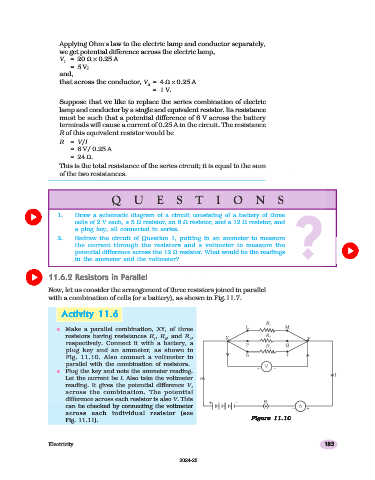
11.6.2 Resistors in Parallel
Now, let us consider the arrangement of three resistors joined in parallel
with a combination of cells (or a battery), as shown in Fig.11.7.
Activity
Activity 11.611.6
Activity 11.6
11.6
Activity
Activity 11.6
n Make a parallel combination, XY, of three
resistors having resistances R , R , and R ,
1 2 3
respectively. Connect it with a battery, a
plug key and an ammeter, as shown in
Fig. 11.10. Also connect a voltmeter in
parallel with the combination of resistors.
n Plug the key and note the ammeter reading.
Let the current be I. Also take the voltmeter
reading. It gives the potential difference V,
across the combination. The potential
difference across each resistor is also V. This
can be checked by connecting the voltmeter
across each individual resistor (see
Figure 11.1011.10
Figure
Figure
11.10
Figure 11.10
Fig. 11.11). Figure 11.10
Electricity 185
2024-25