
Page 186 - NCERT Science Class 10 English Medium
P. 186
Q U E S T I O N S
1. On what factors does the resistance of a
conductor depend?
2. Will current flow more easily through a thick
wire or a thin wire of the same material, when
connected to the same source? Why?
3. Let the resistance of an electrical component
remains constant while the potential difference
across the two ends of the component
decreases to half of its former value. What
change will occur in the current through it? ?
4. Why are coils of electric toasters and electric
irons made of an alloy rather than a pure
metal?
5. Use the data in Table 11.2 to answer the
following –
(a) Which among iron and mercury is a better
conductor?
(b) Which material is the best conductor?
11.6 RESISTANCE OF A SYSTEM OF RESISTORSANCE OF A SYSTEM OF RESISTORS
11.6 RESISTANCE OF A SYSTEM OF RESISTORS
11.6
11.6 RESISTRESISTANCE OF A SYSTEM OF RESISTORSANCE OF A SYSTEM OF RESISTORS
11.6 RESIST
In preceding sections, we learnt about some simple electric circuits. We
have noticed how the current through a conductor depends upon its
resistance and the potential difference across its ends. In various electrical
gadgets, we often use resistors in various combinations. We now therefore
intend to see how Ohm’s law can be applied to combinations of resistors.
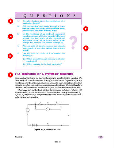
There are two methods of joining the resistors together. Figure 11.6
shows an electric circuit in which three resistors having resistances R ,
1
R and R , respectively, are joined end to end. Here the resistors are said
2 3
to be connected in series.
Figure 11.611.6
Figure 11.6
11.6
Figure 11.6 Resistors in series
Figure
Figure
Electricity 181
2024-25