
Page 181 - NCERT Science Class 10 English Medium
P. 181
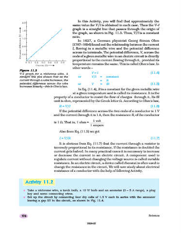
In this Activity, you will find that approximately the
                                                  same value for V/I is obtained in each case. Thus the V–I
                                                  graph is a straight line that passes through the origin of
                                                  the graph, as shown in Fig. 11.3. Thus, V/I is a constant
                                                  ratio.
                                                     In 1827, a German physicist Georg Simon Ohm
                                                  (1787–1854) found out the relationship between the current
                                                  I, flowing in a metallic wire and the potential difference
                                                  across its terminals. The potential difference, V, across the
                                                  ends of a given metallic wire in an electric circuit is directly
                                                  proportional to the current flowing through it,  provided its
                                                  temperature remains the same. This is called Ohm’s law. In
                                                  other words –
              Figure
              Figure 11.311.3
              Figure 11.3
              Figure
              Figure 11.3
                     11.3
              V–I graph for a nichrome wire. A                V ∝ I                                   (11.4)
              straight line plot shows that as the   or       V/I   =   constant
              current through a wire increases, the                 =   R
              potential difference across the wire   or       V     =   IR                            (11.5)
              increases linearly – this is Ohm’s law.
                                                     In Eq. (11.4), R is a constant for the given metallic wire
                                                  at a given temperature and is called its resistance. It is the
                                     property of a conductor to resist the flow of charges  through it. Its SI
                                     unit is ohm, represented by the Greek letter Ω. According to Ohm’s law,
                                         R = V/I                                                      (11.6)
                                         If the potential difference across the two ends of a conductor is 1 V
                                     and the current through it is 1 A, then the resistance R, of the conductor
                                                               1 volt
                                     is 1 Ω. That is, 1 ohm =
                                                             1 ampere

                                         Also from Eq. (11.5) we get

                                         I = V/R                                                      (11.7)
                                         It is obvious from Eq. (11.7) that the current through a resistor is
                                     inversely proportional to its resistance. If the resistance is doubled the
                                     current gets halved. In many practical cases it is necessary to increase
                                     or decrease the current in an electric circuit. A component used to
                                     regulate current without changing the voltage source is called variable
                                     resistance. In an electric circuit, a device called rheostat is often used to
                                     change the resistance in the circuit. We will now study about electrical
                                     resistance of a conductor with the help of following Activity.


                  Activity 11.211.2
                  Activity
                  Activity    11.2
                  Activity 11.2
                  Activity 11.2
                 n Take a nichrome wire, a torch bulb, a 10 W bulb and an ammeter (0 – 5 A range), a plug
                   key and some connecting wires.
                 n Set up the circuit by connecting four dry cells of 1.5 V each in series with the ammeter
                   leaving a gap XY in the circuit, as shown in Fig. 11.4.


               176                                                                                   Science


                                                           2024-25